Machine Vice Models and Drawings Re. Depending on the material being drilled and the size of hole it is usually safe to hold the vice in the hand by the handle and not necessary to bolt it to the drilling table.

Swivel Machine Vice 3d Cad Model Library Grabcad
This design represents a mechanical bench vice.

. Tools vise 69 Likes. This video make by Vishwakarma Engineering Drawing Classes Bhilai Nagar. Vises have two parallel jaws one fixed and the other movable threaded in.
Fundamentals of Graphics Communication Gary R. Most homeowners bench vices have an exposed screw. Machine components done using conventional drawing board and AutoCAD Assembly drawing from working drawing.
Fig- 1 shows a machinist bench vise with swivel base. A heavy swivel bench vise modeled in Alibre from drawings in Advanced Mechanical Drawing - Part 2 International. Machine vice Machine vices are hooked up on.
With the use of CAD software CATIA V5R18 it includ es. Our swivel base design allows for positioning in 1 increments making it easy to align your vise and workpiece just the way you need it. Part drawing from assembly drawing.
A swivel machine vice assembly consisting of - Body Swivel Base Moving Jaw Jaw Plate X 2 Screw Rod Moving Jaw Base Clamp X 2 Clamping Bolt X 2 Clamping Nut X 3 Jaw Plate Screw X 4 Moving Jaw Bolt X 2 Screw Rod Washer Softwares Used. The small bolts are loosened allowing the main body of the vice to swivel 360 degrees. 8 vice body 1 9 vice jaw 1 10 clamping plate 1 2 1 a b a b 2 1 do not scale drawing vice assembly drawing sheet 1 of 1 cory j 11182016 unless otherwise specified.
INTERPRET TOLERANCES FfR AND EDGES MATE RIAL steel Isu Working Drawings Project 216 PART UMBER MATERIAL Mid Mid Mid Mia Mid Mid SCALE 1 SCALE 2 Isu Working Drawings Project Precision Vte. Dimensions to indicate range of motion or overall size of assembly for reference purposes. The vise can secularly fasten castings forgings and roughed surface work pieces.
The jaws can be positioned between. Some engineers vices marketed as Homeowner Grade are not made of steel or cast iron but of pot metal or a very low grade of iron typically with a tensile strength of under 10 ksi. Size of the file.
Up to 24 cash back SWIVEL VISE. The Swivel Vise can be rotated and contains a scale graduated in degrees at its base to facilitate machining at any angle on a horizontal plane. Machine design Tools Tags.
A heavy swivel bench vise modeled in Alibre from drawings in Advanced Mechanical Drawing - Part 2 International Textbook Press. Swivel Machine Vice Assembly Major Project. More by William Heidt.
Solidworks assembly sldasm and Solidworks part sldprt User purpose of file. Assemble theparts and draw the following views to a suitable scale. It consists of the base 1 which isclamped to the machine table using two T-bolts.
Assembly Drawings must provide sufficient information to enable the assembly of a component. Four different models are available to fit different Kurt. Rev a size title.
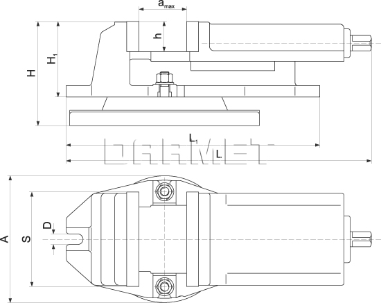
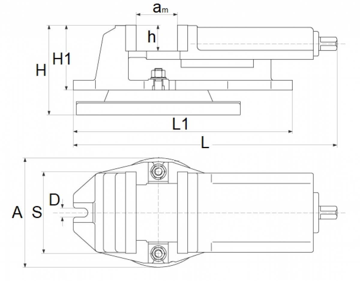
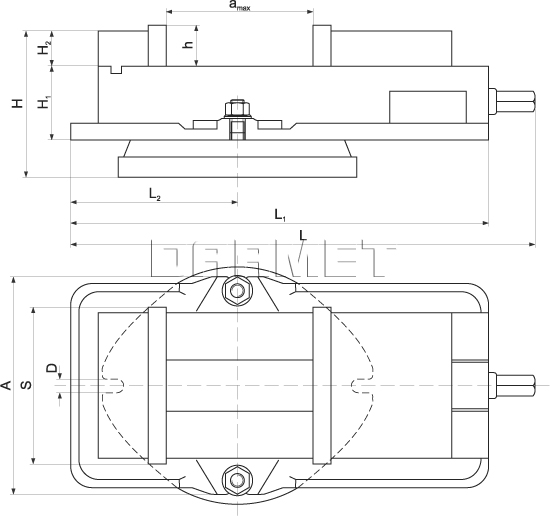
Most engineers vices have a swivel base. Assembly Drawings must have a number of views to show how parts fit together. On this drawing the location and dimensions of few important parts and overall dimensions of the assembled unit are indicated.
Watch to find how to Design bench vice in solidworks including all vice parts design and assemble with easy to follow stepsThis solidworks tutorial starts w. Swivel bearing Machine Swivel vice Tool head of shaper Tailstock Fuel pump Fuel Injector Rams bottom safety valve Stop valve Blow-off cock Screw Jack Centrifugal pump. Set screw scale 11 12 216-24unc-2a.
Checked drawn finish material interpret geometric tolerancing per. Vise 35023 views - Mechanical Engineering A vise American English or vice British English is a mechanical apparatus used to secure an object to allow work to be performed on it. This drawing provides useful information for assembling the machine as this drawing reveals all parts of a machine in their correct working position.
The Part-B assignment involves in creatio n of the assembly drawing of the swivel machin e vise. Can be used edited and use for more purpose. To provide precise positioning of your vise while working Kurt Workholding offers specially-designed swivel base assemblies.
2x drill and csk for 14 fl hd mach scrw. Dimensions are in. With a complete design and dimensional all in Solidworks 2007.
MACHINE VICE ASSEMBLY. Section views to show how parts fit and to eliminate hidden detail. ¾ Creation of individual elements of the.
View Group 8 Task Allocation Documentdocx from CPTR 235 at Northern Caribbean Univeristy. 1234 Installation Assembly Drawing. This heavy duty machine vice can be set at a variety of horizontal angles.
I Half sectional view from the front with top half in section and ii View from the left1839 Machine ViceThe details of a plain machine vice are shown in Fig. The assembly of tool named machine vice which is used for clamping the workpiece along with other parts required to complete the model. 2x 37 drill with part 8 in place.
Swivel Machine Vise 80mm Fq80 65 Darmet

Machine Vice 3d Cad Model Library Grabcad

Fig2 19 Assembly Of Swivel Vise Download Scientific Diagram
Cormak 200 Mm Swivel Machine Vice

Fig2 19 Assembly Of Swivel Vise Download Scientific Diagram
Swivel Machine Angle Lock Vise 200mm Fqm200 200 Darmet

Swivel Machine Vice 3d Cad Model Library Grabcad

Assembly Drawing Of Plain Machine Vice Youtube
0 comments
Post a Comment